Polyvinyl chloride (PVC) and chlorinated polyvinyl chloride (CPVC) are common thermoplastic piping materials used in both residential and industrial applications. These materials exhibit good corrosion resistance and are lightweight, easy to handle and install, and require low maintenance. Often, PVC and CPVC piping are used in plumbing, water supply, and wastewater treatment. There are numerous standards and specifications available for PVC/CPVC pressure piping systems. When working with these materials, it is important to reference these standards, which can be found within many manufacturers’ technical manuals.
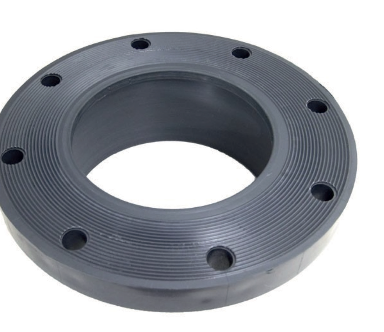 Figure 1: Flat-face one-piece flange. Source: 8” Schedule 80 PVC Slip Flange 851-080 (pvcfittingsonline.com)
Background
CPVC is a version of PVC that has undergone an additional chlorination reaction. The higher chlorine concentration of CPVC slightly alters and enhances its mechanical and performance characteristics related to chemical compatibility, temperature resistance, and tensile strength. While both materials are generally fairly brittle (and increase in brittleness over time), CPVC is substantially more flexible than PVC.In North America, most PVC & CPVC joints are bonded with a solvent cement. This results in a chemical fusion that provides a reliable and leak-free method to connect pipe and fittings. In fact, there is a whole other procedure dedicated just to this bonding process. However, there are instances where a flanged joint is either necessary and/or advantageous compared to a bonded joint, such as: when frequent disassembly is expected for cleaning, maintenance, or replacement; or if connecting to dissimilar piping/equipment.
Flanges can be a one- or two-piece design. One-piece flanges can be raised or flat-faced with the fitting mounting directly to the pipe (see Figure 1). This pipe connection can be a socket (slip fitting) or a threaded fitting. A socket/slip fitting is a ‘female’ type fitting which is mounted directly to the exterior of the pipe and then ‘solvent welded’ (i.e., bonded with solvent cement) in place. Conversely, the threaded fitting requires no glue or solvent cement. See Figures 2 and 3 for the one-piece flange examples.
In the PVC/CPVC world, two-piece flanges are referred to as Van Stones. Similar to a traditional lap joint, this design consists of a stub end and the flange. Like the one-piece design, the Van Stone stub end is available in both the socket and threaded versions, as well as a spigot flange. The spigot flange is essentially the ‘male’ fitting version of the socket flange (see Figures 4 and 5). Its end matches the OD of the pipe and is typically connected to the pipe through a double female hub or coupling, which is then solvent welded together. Since the Van Stone flange is not directly attached to the stub end, it can be freely rotated which gives it an advantage over the one-piece design when installing, aligning, and mating flanges. Another advantage of the Van Stone is that if the flange cracks, breaks, or becomes otherwise defective, the flange can be swapped out for a new split ring replacement flange (Figure 7) without having to cut off the stub end to install a new flange. This can be a significant time saver as the curing requirement for the solvent welding process can take hours or even days, depending on conditions. Many manufacturers also offer a ‘webbed’ version of their flanges (Figure 8). This option uses less material and results in less deformation in the manufacturing process.
Assembly Procedures
Best practices for assembling PVC/ CPVC flanges begins by referring to the manufacturer’s recommendations. Most, if not all, manufacturers have their own set of guidelines, tips, procedures, and torque values that are readily available online. However, it is important to recognize that many published torque values do not specify whether they apply to raised-face or flat-faced flanges.Additionally, the goal of these prescribed values is to preserve the integrity of the flange, not necessarily to provide optimized sealing of the joint. Therefore, best practices also require a thorough analysis of the resultant gasket stresses developed. This will ensure that the gaskets can reach an acceptable level of sealing stress.
For example, after analyzing the developed gasket stresses using one manufacturer’s torque table, several deficiencies were observed. Full-face gaskets (with a large sealing area) were underloaded, whereas ring gaskets (with a small sealing area) were pushing the upper compression limits for elastomeric gasket material. In a high stress scenario, the target torque can simply be reduced to a suitable level. For the low stress scenario, however, the solution is not as simple. Either the area of the gasket should be reduced (custom-sized gasket) or the manufacturer should be consulted to determine alternative options.
Elastomeric gaskets, 1/8” thick, are commonly recommended for PVC/ CPVC piping applications, but in some of the more corrosive applications, a PTFE-lined elastomer or ePTFE-based gasket might be necessary. Again, it is important to review the gasket’s stress requirements in these cases, especially the ePTFE-based gasket, as it has a minimum sealing stress that can be as much as ten times greater than some elastomers.
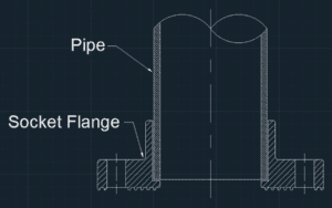 Figure 2: One-piece socket flange. Source: Teadit.
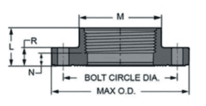 Figure 3: One-piece threaded flange. Source: 2 S80 CPVC FPT FLANGE 852-020C 980372 25900, CPVC Threaded Flanges (bpssg.com)
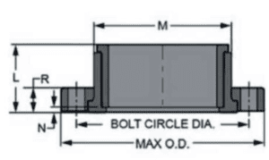 Figure 4: Van Stone socket flange. Source: Spears® 854-040C 2-Piece Van Stone Flange, 4 in, CPVC, Socket, 9 in OD, Domestic | First Supply
 Figure 5: Van Stone spigot flange. Source: Flanges & Cut-In Kit (spearsmfg.com)
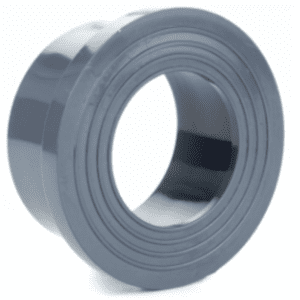 Figure 6: Socket stub end. Source: PVC Flange | Stub Inch | PVCu (pipestock.com)
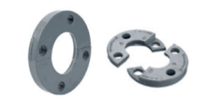 Figure 7: Van Stone flange replacement split rings. Source: SCH80CPVC_80C-1_FLRSR-1.pdf
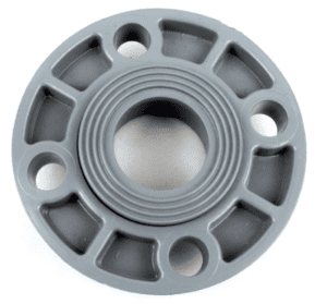 Figure 8: Van Stone webbed socket flange. Source: +GF+ Georg Fischer 9854-015 1-1/2’’ Van Stone Flange Socket CPVC SCH-80 (industrial-stores.com)
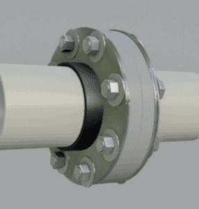 Figure 9: Metallic backup rings used to help reduce risk of flange flexion. Source: 3.13 Inch (in) Inside Diameter (I.D.) Carbon Steel Two-Piece Backing Ring Flange – The Marzolf Company
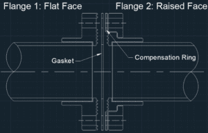 Figure 10: Flat-face flange mated to a raised-face flange. Source: Teadit.
Before starting any assembly process, it is critical that all solvent welded joints have had time to properly cure, that any threaded fittings or flanges on the joint in question have been properly tightened, and that the flanged joint’s adjacent piping is properly supported. A wet, tacky, or movable joint would indicate that the joint has not yet properly cured. For threaded joints, a loose or movable fitting or flange would indicate that further tightening is required.
If excessive pipe movement is observed when torquing, stop the job and readjust the supports. This will help to ensure that the piping is not damaged during flange assembly. When working with plastic flanges, concentrated loads and flange flexion/rotation are the assembler’s worst nightmare during the bolting process; therefore, it is a best practice to use washers and metallic backing rings (see Figure 9), especially in critical processes where pipe integrity and flange leakage are of high concern. Washers are important as they help to better distribute the load imparted by the nut, and they also eliminate the risk of damaging the flange during nut rotation. Similarly, the metallic backing ring will also help to distribute the forces across the flange. Though, the main benefit of the backing ring is that, because it is a stronger, stiffer material, it will reduce the risk of excessive flange flexion.
Like any other flange assembly, it is important to ensure flanges are aligned and that the faces are parallel, with just enough gap to fit the gasket in between them. Best practice for most bolted flange assemblies should include lubrication, however, even today’s manufacturers still publish torque charts for dry fasteners, or worse yet, without specifying dry or lubricated fasteners. At the same torque value, lubricated fasteners will result in substantially more bolt load and compressive load than dry fasteners would allow, which could damage the PVC/CPVC flanges. If a torque chart does not explicitly call for either dry or lubricated fasteners, check with the manufacturer first. If lubrication is to be used, be sure to lubricate the bolt/stud and nut threads, as well as the bottom face of the nut (to minimize friction against the washer or backing ring). Prior to starting the torquing procedure, the nuts should be hand-tightened. Be sure to follow the manufacturer’s recommendations for the torquing procedure and torque values. It should generally consist of three star pattern passes starting at approximately 30% of the target torque, then 60% for the second star pass, and then 100% for the last star pass, followed by at least two circular passes at 100% of the target torque.
If there is still excessive nut rotation on the second circular pass, continue the circular passes at 100% of the target torque. Because there can be some loss of bolt stress due to relaxation of the plastic components, it is always recommended to perform a retorque after 24 hours at 100% of the target torque. If this is not possible, a retorque at one, two, or four hours after assembly will always be better than no retorque at all. Never exceed the manufacturer’s maximum target torque without the manufacturer’s approval.
In mating a flat-faced flange to another flat-face, there should be no gap between the flanges and gasket. Any gap will allow for a bending moment in the flange during the torquing procedure, which is a recipe for disaster when dealing with brittle flange materials. There may be instances, however, when a flat-faced flange (PVC/CPVC) is mated to a raised-face flange (see Figure 10). Inherently, there will be a gap between the raised-face flange and the gasket. This space can allow room for the flat-faced flange to rotate/flex and ultimately crack. Therefore, it is imperative to convert the raised-face flange to a flat-face through the use of a ‘compensation’ ring, which fits outside of the raised-face surface with the same bolt hole pattern as the flanges.
Getting the right thickness for the compensation ring can be a tricky trial-and-error situation, but it is necessary to get the raised-face flange as flat as possible without creating a high point (concentrated load) or leak path. With the gasket and compensation ring in place, assemble to the weakest component’s limit. When mating raised-face to raised-face, there will still exist a gap. Van Stone flanges, however, are designed for this gap and are less susceptible to cracking, mostly because they are not rigidly attached to the stub end; there is more leeway for flange flexion or movement. Lastly, on older PVC/ CPVC systems, white or ‘washed out’ lighter gray color can indicate UV-degradation, which results in embrittlement and deterioration of strength. If working with older piping or flanges that exhibit these colors, be aware that replacement may be necessary.
Discussion
Teadit purchased PVC and CPVC blind flanges from several different manufacturers with the intent to perform gasket testing. When the flanges arrived, it was observed that the flanges had significant differences among their contact (raised face) surfaces. For instance, the surface area for a standard 6” 150# RF flange is 22.3 in2, however one manufacturer’s flange of this size had a contact surface area of only 5.6 in2. Ultimately, it was concluded that such differences between manufacturers would compromise any sealability testing such that no trustworthy comparison or conclusions could be taken from the tests.When purchasing PVC/CPVC piping system, it is recommended to perform a thorough review of the dimensions prior to purchase, as well as confirming that the delivered product meets those requirements, and that any prescribed torque values/tables are suitable for both the flange and gasket to ensure a good seal. Future maintenance and/ or partial replacement might require using the piping’s original manufacturer, or at least executing another thorough review to certify that the new materials meet expectations.
Following these best practices will help to ensure that a PVC/CPVC piping system remains reliable and leak-free throughout its life. Because there is so much variability between manufacturers, it is always best to consult with the manufacturer of a piping system to address any questions or concerns.
 About the Author
Jon Meyer is a Sales Engineer with Teadit. From Process Operator to Reliability Engineer, Jon has worked for nearly 20 years in the chemical manufacturing industry and holds a BE degree in mechanical engineering. As a Reliability Engineer, he was primarily focused on fixed equipment, Bolted Flange Joint Assembly training, procedures and torque calculations, 3D modeling, FEA for design and fabrication, heat exchanger design, glass-lined equipment, and non-metallics.