The world is in a race to secure a clean energy transition. Many view green hydrogen, which is produced by a water electrolysis process that is powered by renewable energy, as a key technological contributor to reaching net zero emissions. As electrolyzer manufacturers advance existing technologies, develop new ones, and ramp up their production capacities to meet the surging demand, the need for electrolyzer components is following suit.
Large electrolyzer and fuel cell stacks can be comprised of several hundreds of individual cells that must be properly sealed to ensure safe and efficient operation. The opportunity for companies to accelerate the scale-up of green hydrogen production globally is immense. In the coming years an overall growth of the cumulated capacity of electrolyzers is expected to reach a benchmark of over 200 GW in 2030.
Currently, industrial H2 comes from a variety of sources, with the majority (48%) produced by the reforming of natural and/or refinery gas (known as grey H2). Other major sources include chemical production by-products (30%, white H2) and coal gasification (18%, brown H2). Only about 4% of global hydrogen production currently comes from electrolysis. Moreover, segmenting based on the source of the power used to drive the production, the hydrogen color palette contains even more variations. For example, purple H2 is produced using nuclear power and yellow H2 production utilizes a mixture of renewables and fossil fuels. However, achieving truly climate neutral H2 production requires that the electricity used for water electrolysis must be ‘green’ and therefore produced only from renewable energy sources, such as solar conversion (PV), or wind, or water driven turbines. This is one of the most proven options for low-carbon hydrogen and plays a key role in mobility, industry, or energy storage scenarios today.
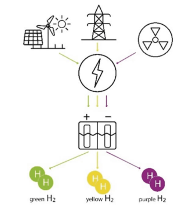 Figure 1: Color palette: selected production options of Hydrogen from electrolysis.
Electrolyzers can be scaled to meet a variety of input and output ranges. They vary in size from small industrial plants installed in shipping containers to largescale centralized production facilities that can deliver the hydrogen by trucks or be connected to pipelines.
There are three main types of electrolyzers:
- alkaline,
- proton exchange membrane (PEM),
- and solid oxide.
H2 Electrolyzers Explained
Alkaline electrolyzers use a liquid electrolyte solution such as potassium hydroxide (KOH) or sodium hydroxide (NaOH), and water. The hydrogen is produced in a ‘cell’ which consists of an anode, cathode, and membrane. The cells are typically assembled in series, a ‘cell stack,’ that produces more hydrogen and oxygen as the number of cells increases. When current is applied on the cell stack, the hydroxide ions (OH) move through the electrolyte from the cathode to the anode of each cell, which generates hydrogen gas bubbles on the cathode side of the electrolyzer and oxygen gas at the anode.PEM electrolyzers utilize a proton exchange membrane which uses a solid polymer electrolyte. When current is applied on the cell stack, the water splits into hydrogen and oxygen and the hydrogen protons pass through the membrane to form H2 gas on the cathode side.
One of the most important considerations in electrolysis applications is the technical requirements for the gaskets used in sealing the individual cells withing the stack. Due to its excellent sealing properties, PTFE has become a common gasketing material of choice. The seals used in the past were often made of asbestos coated with PTFE. Nowadays, however, asbestos is no longer used, so gaskets made of expanded or restructured PTFE have become a standard alternative.
Advanced PTFE solutions are universally employable for a variety of electrolyzer applications. They are suitable for all types of flanges, nearly all media, a wide temperature range, and for applications with high purity demands as they are inherently clean and non-toxic. Furthermore, they demonstrate high tightness (sealability) with low installation stresses even in media with small-sized molecules, like H2; and mechanical stability to creep relaxation.
Additionally, any potential seals applied in electrolyzer stacks must be electrically non-conductive to isolate the anode from the cathode. In general, the PTFE fluoropolymer offers remarkable dielectric strength and high resistance. To address the most diverse and challenging industrial applications a wide range of expanded PTFE (ePTFE) sealing products have been developed and manufactured.
ePTFE: What is it and How is it Made
All-purpose mono-directionally expanded PTFE sealant products (Figure 2, left) are manufactured from 100% pure PTFE (polytetrafluorethylene). Utilizing a special, thermo-mechanical stretching process results in a microporous fiber structure which adds high tensile strength and malleability to the previously identified general advantages of PTFE; while at the same time virtually eliminating the negative characteristics, like cold flow and creep. Because of the excellent compressibility and conformability of ePTFE, these sealant products adapt easily to the individual installation structures that are necessary, for example, in electrolyzer production. Figure 2: Presentation of three different types of ePTFE products. Left: mono-directional, middle: multi-directional; right: structured.
The benefits to the cold flow properties and deformation characteristics developed by monoaxially expanded PTFE sealants are further improved by adapting the manufacturing process to incorporate expansion in multiple directions. This complex stretching process results in a multi-directional fiber structure which guarantees equal tensile strength in all directions, Figure 2, middle. This material has excellent dimensional stability and exhibits superior creep resistance, without losing any of the superb sealing properties of pure PTFE. Therefore, ePTFE products are ideally suited for use in H2 applications.
In addition to ePTFE sealing products, restructured PTFE materials, Figure 2, right, developed using a unique production process that develops a highly fibrillated PTFE structure combined with carefully chosen filler materials, offer a more rigid and higher density option with very high mechanical strength to improve handling. The caveat with these products is that the filler materials must be chosen for compatibility with the application for which they will be used.
Tested and Approved to Seal the ‘Smallest Molecule’
One useful tool for determining a material’s suitability in H2 applications is lab testing. However, most available tests do not utilize hydrogen as a test media. Therefore, engineers undertook a special investigation to determine how these products might perform. The aim of the investigation was to determine the gasket parameters according to the European test standard DIN EN 13555. This information is required for calculations according to DIN EN 1591-1 and is necessary for the approval of gasket solutions to seal hydrogen.The conditions that are determined through this testing standard include a minimum gasket surface pressure in the assembled state Qmin(L) (40 bar) and minimum gasket surface pressure in the operating condition Qs, min(L) (40 bar). Deviating from the test standard, the leakage tests were carried out using hydrogen (H2).
In the leakage test, the gasket is loaded and unloaded in several stages, with the leakage rate being determined for each gasket surface pressure level. The measurement is carried out up to a gasket surface pressure of 160 MPa. The test records not only the loading curve, but also several unloading curves based on gasket surface pressure levels of 20 MPa, 40 MPa, 60 MPa, 80 MPa, 100 MPa, 120 MPa and 160 MPa. The smallest surface pressure level is 10 MPa.
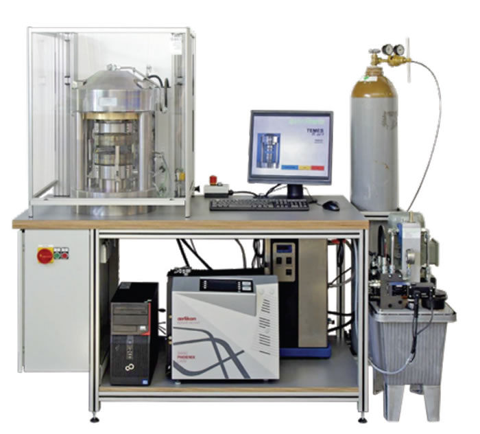 Figure 3: Presentation of the test equipment: gasket tests are driven with this test station (TEMESfl.ai1) in the laboratories of Amtec.
Gasket tests were carried out on a TEMESfl.ai1 test equipment at Amtec‘s test laboratories, Figure 3. For several decades, Amtec has been testing the properties of gaskets, calculating strength, and measuring bolt forces.
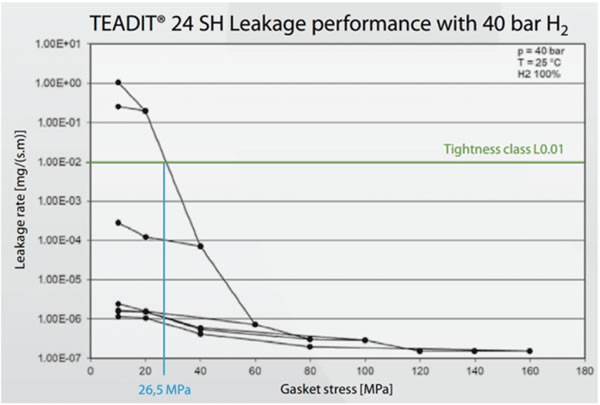 Figure 4: Presentation of the gasket stress test of an ePTFE gasket (24 SH) with 40 bar H2 pressure at room temperature. The green line represents the tightness class L0.01 (TA-Luft), the blue line highlights the surface pressure at the required tightness level.
The resulting leakage curve can be used to calculate the required minimum gasket surface pressure Qmin (L) for the various tightness classes, L, during assembly and the required minimum gasket surface pressure Qs, min(L) during operation. In the testing of a biaxially expanded ePTFE gasket (Teadit Style 24SH), the tightness class L0.01 was achieved at a the test pressure of 40 bar and a gasket surface pressure of 26–27 MPa. As the gasket is further loaded up to 160 MPa, the leakage rate decreases. The lowest leakage rate was measured at the surface pressure level of 160 MPa with 1.5 x 10⁻⁷ mg/s/m. The required minimum gasket surface pressure Qs min(L) in the operating state for tightness class L0.01 with an initial gasket surface pressure QA = 60 MPa is Qs min (0.01) = 10 MPa. The results are presented in the graph below, Figure 4.
Looking to the Future
Currently, the hydrogen demand is growing globally while activities in electrolyzer production are still in the early stages. However, as the energy transition accelerates, it is expected that massive amounts of resources will be allocated for developing new technologies, including developments in green electrolyzer technologies. The foundations of these future advancements are being seen today with major industrial manufacturers directing money and resources into reducing carbon output. As this happens, the requirement for H2 compatible sealing solutions is expected to develop concurrently in the coming years. The readiness to deliver high-end PTFE and ePTFE products that are suitable for the applications in electrolyzers will be paramount to the continued growth and expansion of this largely untapped resource. About the Author
Johannes Müller is the Energy Transition Manager at TEADIT International Produktions GmbH in Kirchbichl, Tyrol, Austria. Before joining the Teadit Group, Johannes studied chemistry at the Friedrich-Alexander-University (FAU) in Germany and will be finalizing his studies as a PhD this summer.