Bolted flange joint assemblies (BFJAs) and valve stem packing systems form the critical sealing interface in pressurized piping networks, vessels, and heat exchangers. While they differ in geometry and sealing dynamics, both systems depend on proper gasket or packing stress and material selection to create a long-lasting seal. The reliability of these sealing devices is contingent not only on engineering design but also on how proactively those components are selected, installed, torqued, and monitored. Depending on the material and joint design, components may require retorquing after the initial installation. This can be done as a corrective action in response to leakage, or as part of a planned maintenance or relaxation compensation procedure.
While much of the existing literature focuses on retorque as a corrective practice, a growing body of field experience and controlled testing reveals the need for proactive retorquing strategies. In other words, rather than waiting for a leak to occur, the joint is retorqued after a predefined time interval based on material behavior, application demands, and manufacturer recommendations. Adopting and implementing these strategies ensures preload integrity and sealing performance from the onset, rather than reacting to leaks or emissions after they occur.
By adopting best available technologies such as TEADIT®’s wide range of sealing solutions, companies are enabled to prevent leaks before they occur. This reduces emissions and product loss, and ensures that the best maintenance processes are followed from the point of installation, to the foreseeable future.
Relaxation: Known, Predictable, and Preventable
Gasket, packing, and bolt relaxation are well-understood physical processes. Load loss can result from material creep, thermal expansion, and deformation under compressive stress. Proactive planning can make the difference between a reliable, long-term seal and a premature failure.
Gasket relaxation is highly dependent on material type. Soft, nonmetallic sheet gaskets (e.g. PTFE, compressed fiber, etc) are particularly prone to relaxation, even at ambient temperatures. However, not all materials perform equally. For instance, skived PTFE can be inexpensive but tends to exhibit significantly higher relaxation than both expanded PTFE (ePTFE) or restructured PTFE (rPTFE), which are engineered to offer better load retention. Semi-metallic gaskets, such as spiral wound gaskets (SWGs) and Kammprofiles, are comparatively more resistant to relaxation. In these cases, relaxation typically becomes a concern only at elevated temperatures, generally above 500°F (260°C). For flanged joints, early-stage gasket relaxation can reduce bolt load by 10–20% within the first few hours after installation, potentially compromising sealing performance if not accounted for.
For valve stem packing, the initially applied gland load is intended to consolidate the packing rings and achieve the target packing density required to maintain a reliable seal. However, upon system startup, valve actuation during the first few cycles often leads to an immediate reduction in packing stress. This occurs in large part due to material consolidation and frictional behavior between the stem and packing rings.
To address this, packing manufacturers recommend cycling the valve a few times immediately after packing installation and initial tightening. Once the packing has been consolidated, the target gland load should be reapplied (with a retorque).
Sheet Gaskets and Packing Materials: The Material Matters
Material formulation and manufacturing method play a crucial role in gasket relaxation behavior. As mentioned earlier, while skived PTFE, expanded PTFE (ePTFE), and restructured PTFE (rPTFE) are all comprised of the same base polymer, their mechanical performance under load varies significantly. These differences become even more pronounced when compared to semi-metallic gaskets.
To evaluate these effects, TEADIT® conducted controlled testing using a flange test rig equipped with instrumented bolts. This setup allowed continuous monitoring of bolt load during installation and throughout the relaxation period. Each gasket material was tested in five different retorque conditions: no retorque, and retorque applied at 15 minutes, 1 hour, 4 hours, and 24 hours after initial installation. After the final retorque, the assembly was left undisturbed for 20 hours, at which point the remaining bolt stress was recorded. The entire test was executed at ambient temperature.
- ePTFE experienced a 12.6% loss in bolt stress with no retorque. When retorqued 15 minutes after installation, the loss dropped to 7.5%. Delaying the retorque for a full 24 hours reduced the stress loss even further to 3.0%.
- rPTFE performed similarly, showing a 12.5% stress loss without retorque, 7.8% with a 15-minute retorque, and 4.4% when retorqued after 24 hours.
- ePTFE and rPTFE exhibited comparable performance, this is likely due to both materials being produced with high-quality resins and engineered microstructures. Skived PTFE, by contrast, showed a much higher stress loss of 20.0% with no retorque. A 15-minute retorque reduced that to 12.3%, while waiting 24 hours before retorquing brought the loss down to 8.0%, still roughly double the loss observed in ePTFE and rPTFE.
- Semi-metallic gaskets showed superior performance overall. The spiral wound gasket (SWG) exhibited a 3.8% stress loss with no retorque, which improved to 2.2% after a 24-hour retorque. The kammprofile gasket started at 3.6% stress loss without retorque and improved to just 0.7% after a 24-hour retorque.
- These results highlight the importance of both material selection and retorque strategy in achieving and maintaining long-term sealing performance.
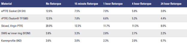
Table 1. Relative stress loss [%] recorded for each material in the different testing conditions.
Dwell Time and Load Retention in Testing
To expand on the testing results, the stress loss in the different testing conditions can be seen in table 1.
Valve packing exhibits a different behavior, with a significant portion of the stress loss happening during the first mechanical cycles. Either way, the key to both systems is simple: do not torque once and walk away. Let the material settle (dwell) and then re-establish the target sealing stress.
Whether sealing a flange or a valve stem, leak-free startup depends not just on what is installed, but on how, and when, it is torqued. Proactive torque is no longer optional; it is an engineering standard grounded in performance data, compliance risk, and real-world reliability.
Retorque vs. Proactive Torque: A Strategic Shift
While material selection and gasket configuration are essential to joint performance, even the most advanced sealing materials cannot compensate for poor installation practices. Long-term reliability begins with a correctly applied preload. In both bolted flange joints and valve systems, this means applying the right torque at the right time.
A proactive torque strategy follows a defined sequence to account for early gasket relaxation and to maintain preload over time. Key elements include:
- Applying the initial torque using a recommended multi-pass bolting sequence, such as the Star or Quadrant patterns described in ASME PCC-1-2022 Appendix F. This should be followed by a check pass.
- Allowing a dwell period after initial tightening to accommodate gasket embedment and early relaxation.
- Performing a final pass at the target torque after the dwell period.
When necessary, validate the bolt stress digitally using ultrasonic tools or load cells. This improves assembly accuracy by reducing the difference between the estimated bolt load applied by measuring torque and the actual bolt load. This is especially important in emissions-sensitive or critical applications.
ASME PCC-1-2022 outlines best practices for torque application and general bolted flange joint assembly.4 The subcommittee is currently working on revisions to better address bolt and gasket relaxation, with an updated version expected in 2026.
In the meantime, following established best practices, including dwell time and relaxation passes, is strongly recommended. Although a four-hour dwell period is often cited, the data in this article show that even shorter intervals, such as 15 to 60 minutes, can produce meaningful improvements in preload retention for expanded and restructured PTFE gaskets.
In general, longer dwell times provide better results. However, in real-world applications where time is limited, this data allows for more informed decisions that balance performance and practicality.
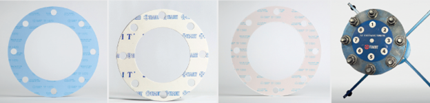
Examples of TEADIT® gaskets used to ensure leak free operations. Pictured left to right: TEADIT®’s TF1570 restructured PTFE with hollow glass spheres as a filler, 24SH, expanded PTFE, and TF1580, restructured PTFE with barite as a filler.
Valve Stems
ASME PCC-1 addresses post-installation retorque for flange assemblies, and a parallel best practice has emerged for valves: a load check or retorque should be conducted not less than three days and not more than two weeks after installation. This timeframe accounts for relaxation effects that occur once the packing is exposed to process temperatures, stem movement, and system pressure. If the load decreases, torque should be reapplied to restore proper compression.
This two-stage torque process is more than a best practice, it is increasingly becoming a compliance expectation. In fact, the U.S. EPA has incorporated similar language into leak detection and repair (LDAR) judicial consent decrees, requiring proactive torque application and post-installation load checks on newly installed or repacked valves to ensure low-emission performance. These protocols are also often prerequisites for product warranties or emissions guarantees offered by valve and packing manufacturers.
Furthermore, historical LDAR consent decrees from the early 2000s acknowledged that many early-stage valve leaks following turnarounds were not material defects, but stemmed from improper installation torque. Some agreements even permitted early leak repair during the first 30 days of startup, recognizing the role of load loss during the break-in period.
Proactive Torque Supports Emissions Control
A proactive torque strategy is not just good maintenance; it is fundamental to emissions compliance. For equipment subject to an LDAR program containing VOCs and benzene, or even equipment in hydrogen service, improperly loaded joints are often the root cause of early-stage leaks.
EPA consent decree data confirms:
- One in seven valves tested post-turnaround leaked due to poor preload control.
- Plants that adopted startup retorque protocols and proactive bolting practices saw measurable reductions in post-install emissions.
- Many leaks are preventable, but often occur because the recommended torque specs were never followed or validated.
Effective preload management, particularly in the critical early hours of operation, determines whether the joint or valve system maintains sealing integrity under real-world operating conditions.
Industry standards such as API 622 and API 624 for valve packing and valves, and ASME B16.20 for spiral wound gaskets, establish a baseline of performance. They provide consistent, repeatable benchmarks that allow for fair product comparison and performance validation. A packing cannot be labeled API 622-approved, nor a gasket stamped with ASME B16.20, without passing these tests. They provide a common performance threshold that gives end users assurance in product selection and allow manufacturers like TEADIT® to engineer solutions that exceed those minimums for even more demanding applications.
However, certification alone does not guarantee emissions compliance in the field. The bridge between lab qualification and operational reliability is closed only through proper installation, proactive torque, and field validation. This is where EPA-approved test methods, namely EPA Method 21 (a quantitative leak detection technique) and optical gas imaging (OGI) (a qualitative visualization tool), play a critical role.
Successful field validation includes verifying installation torque, performing a post-installation retorque or load check, and then confirming emissions performance using either of these field methods. For low emissions service, a properly installed valve or flange that shows < 100 parts per million of hydrocarbon leakage per Method 21, or no hydrocarbon image detected via OGI, is evidence that the system has been sealed to perform as intended over time.
Importantly, this level of control and documentation supports skip-period monitoring protocols allowed under many LDAR programs. When joints and valves consistently demonstrate low emissions performance, the facility benefits from reduced monitoring frequency, lower maintenance overhead, and increased operational confidence.
Ultimately, proactive preload, when paired with qualified materials and validated installation, is what transforms regulatory compliance into sustainable emissions control. The result is fewer leaks, lower operating costs, and greater alignment with the long-term environmental performance goals of modern industrial facilities.
A Unified Strategy for Leak-Free Plants
In the evolving conversation about flange integrity and emissions, torque is no longer just a box to check, it is a precision-controlled element of design, maintenance, and compliance. Whether the goal is leak prevention, emissions reduction, or extended asset life, the message is the same: Do not wait to retorque a leak. Apply the torque that prevents it in the first place.
Start the conversation with your reliability team today to evaluate your current bolting strategy. Contact TEADIT® today to take proactive steps toward achieving leak-free operations.
References
- hextechnology.com/articles/bolted-flange- joint-relaxation-pass
- Girão, C. D., Meira, I. & Veiga, J. C. (2021). Can the Four-Hour Installation Dwell Time Be Reduced? Volume 2: Computer Technology and Bolted Joints; Design and Analysis, V002T02A004. doi.org/10.1115/PVP2021- 61833
- Brown, W, & Lim, T. “Quantifying Bolt Relaxation During High Temperature Operation.” Proceedings of the ASME 2017 Pressure Vessels and Piping Conference. Volume 3A: Design and Analysis. Waikoloa, Hawaii, USA. July 16-20, 2017. V03AT03A031. ASME. doi.org/10.1115/PVP2017-65550
- ASME, 2022, “Pressure Boundary Bolted Flange Joint Assembly”, ASME PCC-1-2022.