In 2011, leaders in the sealing industry performed testing on spiral wound gaskets to see how the winding density affected the sealing behavior. Prior to the work completed by David Reeves with Chevron and Jose Veiga with Teadit, the existing ASME B16.20 standard did not include sealability performance. In fact, a compression test was the only ‘performance testing’ required in that 2007 standard. Updates to the B16.20 standard to include sealability performance came as a result of these tests.
Although there are numerous different variations of spiral wound gaskets, most are produced to the B16.20 standard. As Figure 1 demonstrates, the default components include a sealing element consisting of alternating plies of a metal and a soft filler spirally wound, a metal outer ring (sometimes referred to as a guide ring or a centering ring), and a metal inner ring. The nominal sealing element thickness is 0.175” while both the inner and outer ring thicknesses are 0.125”.
For general service applications, the winding metal is typically a stainless steel or nickel alloy, with flexible graphite or PTFE as the filler. The compression test in the 2007 version of B16.20 standard required a final sealing element thickness of 0.130” ± 0.005” after the gasket was subjected to a compression force, which was based on bolt stress and varied depending on the size and flange pressure class of the gasket.
As with all gaskets and seals, the goal is to provide a leak-free joint. It was hypothesized that the compression test did not necessarily correlate with optimum sealability for spiral wound gaskets. So, the purpose of this study was to determine which winding density, that is the number of metallic windings per unit length, would result in the best sealing performance.
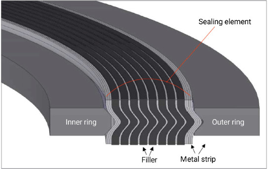 Figure 1: Spiral wound gasket.
Testing
All tests were performed in either a 6” Class 900 or 3” Class 150 forged carbon steel (ASTM A105) ASME B16.5 weld neck, and raised face flanges. The sealing surfaces of the test flanges were 125 – 250 μin, per ASME PCC-1. See Figures 2 and 3 for the test rigs.All stud materials used in testing were ASTM SA-193-B7 with machined ends to allow for precise bolt elongation measurement. The elongation was used to calculate the bolt load and gasket stress. All testing and measurements were taken at room temperature.
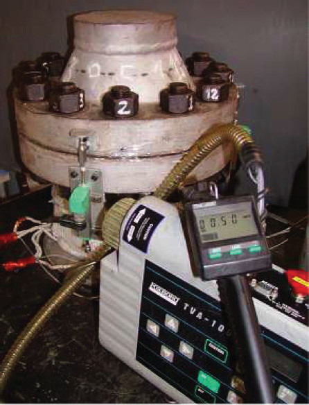 Figure 2: 6” Class 900 test rig.
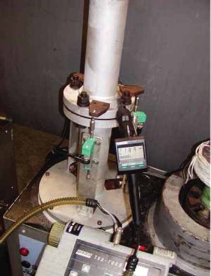 Figure 3: 3” Class 150 test rig.
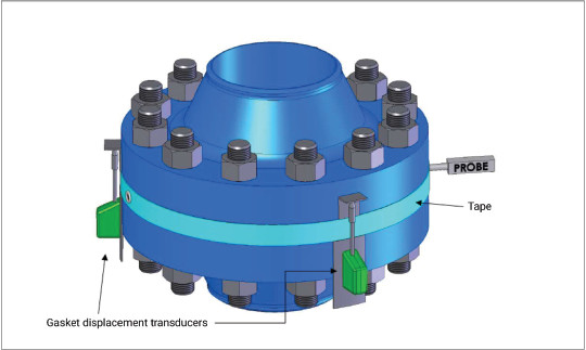
Methane was chosen as the test media. The leak detection measurements were taken with a thermo TVA 1000 volatile organic compound analyzer with readings in parts per million (ppm). The test pressure was 290 psi. To reduce the effect of air currents within the laboratory, the gap between the flanges was sealed with tape, but left with two openings: one for the leak detection probe, and one 180° from the probe to show the methane concentration in a constant flow (see Figure 5).
Sealing any escaping gas and allowing it to accumulate between the flanges ensured that any ppm-level leak would be detected by the analyzer. This method of bagging the leakage results in a global reading, making this setup a more stringent leak-detection method than the localized EPA Method 21.
Along with bolt elongation, gasket displacement was also measured. To do this, transducers were installed on the flange edge, 120° apart.
The gaskets tested all had 304 stainless steel inner rings, 304 stainless steel windings with flexible graphite filler, and carbon steel outer rings. By adjusting the winding force and using different filler thicknesses, multiple winding densities were able to be tested. Tables 1 and 2 show the number of metallic windings per mm (in) in the sealing element for the various low and high-density test gaskets. Gaskets that have more windings per sealing element width have more metallic wraps and therefore a higher density.
All the gaskets tested were manufactured with high-purity flexible graphite filler, which protruded approximately 0.008” beyond the metallic wraps. See Figure 6. In this series of tests, gaskets were installed in the test rigs and then initially compressed to a low gasket stress. Methane at 290 psi (20 bar) was used to pressure up the test rig and, after 30 minutes, the leakage was measured. The gasket was then further compressed to a higher gasket stress and the leakage was measured again. This was repeated numerous times for each test gasket specimen.
The results showed that the winding density with the best sealability was 1.698/mm (43.13/in). After the gaskets were removed from the test rig, it was observed that the low-density gaskets had an imprint on the outer ring, indicating that the flanges were rotating enough to contact the gasket outer ring as shown in Figures 13 and 14. The outer ring thickness for all samples was 3 mm, so any displacement reading less than that indicated flange rotation.
Additional tests were performed to determine if the flange contact with the outer ring was contributing to the sealability of the gasket specimens. To do this, a small groove was machined on both sides of the outer ring as shown in Figure 15.
As shown in Figures 16 and 17, the high-density gasket’s sealability was not affected by the outer ring groove. This indicated that the sealing was provided by the windings. However, the low-density gasket was unable to get a good seal even at high-stress levels. This suggested that the outer ring was essentially acting as a solid metal gasket in the previous low-density gasket tests.
Without the groove, the leakage rates were substantially lower. But sealing on the solid metal outer ring is not considered to be a reliable seal. This is because even a small amount of thermally driven differential expansion between the flanges will eventually cause the metal-to-metal seal to leak. In addition to this, any stampings, scratches, or other imperfections on the outer ring have the potential to be a leak path.
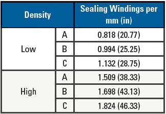 Table 1: Test gaskets for the 6” 900# flange.
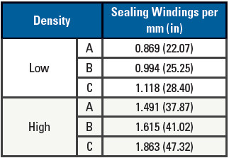 Table 2: Test gaskets for the 3” 150# flange.
Another test was performed with the 6” 900# gaskets to check the validity of the ASME B16.20 compression requirement. As previously mentioned, the 2007 version of ASME B16.20 required that a 30,000-psi uniform bolt stress be applied to a 900# spiral wound gasket that will compress the gasket to a thickness of 3.30 mm ± 0.13 mm. Rather than measuring flange displacement on the outer edge again (and to reduce the effects of flange rotation), a pin was inserted near the weld neck base as shown in Figure 18. Measurements taken at the pin were closer to the actual winding thickness at the corresponding stress.
Figures 19 and 20 show the results from the stress versus displacement tests. In the low-density test, the gasket was compressed 3.3 mm, which met the compression requirements from ASME B16.20-2007, but with a leakage of about 1,400 ppm. In the high-density test, however, the 3.8 mm displacement resulted in a failed test according to ASME B16.20-2007, but the leakage rate was < 10 ppm. These two tests exhibit the problem when testing only for compressibility instead of leakage.
Another requirement from the 2007 version of ASME B16.20 was that ‘the filler shall be essentially flush with, but not below, the metal winding on both contact faces of the gasket’. Gaskets were tested with the filler flush with the metal winding, as shown in Figure 21.
As shown in Figure 22, the high-density gasket, which previously had low leakage even at low gasket seating stresses, did not achieve the same levels of low leakage until the gasket was compressed to much higher seating stress. This suggested that the filler must protrude be- yond the metal windings to achieve optimum sealability at lower stress levels.
Figures 23 – 28 show the results from the 3” 150# gasket testing. This flange size is known for its lower stress limits. The objective with this second set of tests was simply to perform a comparison against the results of the 6” 900# high stress flange.
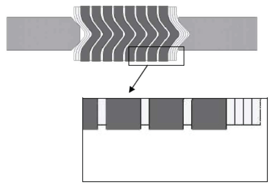 Figure 6: Flexible graphite filler protrusion.
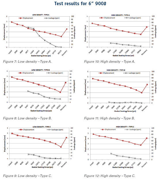
Similar to the results from the 6” 900# spiral wound gasket tests, the 3” 150# gaskets tend to have less leakage when the sealing element had a higher winding density. The flanges never came in contact with the outer ring either, which is corroborated by the displacement values: all of which are greater than 3 mm. Because of this, grooved outer ring testing was not performed.
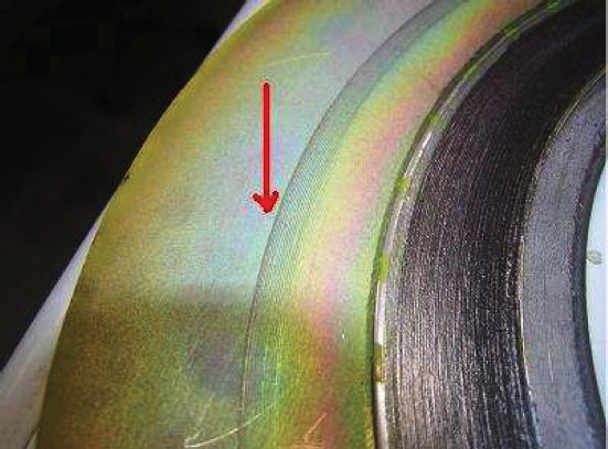 Figure 13: Flange raised face contact imprint on outer ring.
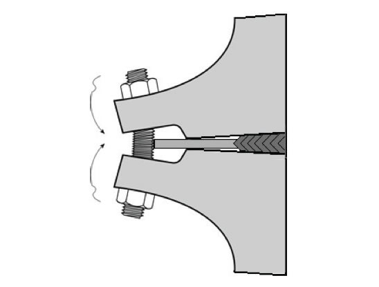 Figure 14: Depiction of flange rotation.
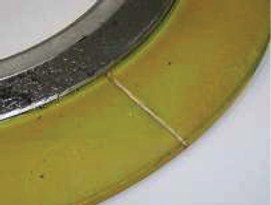 Figure 15: Outer ring groove.
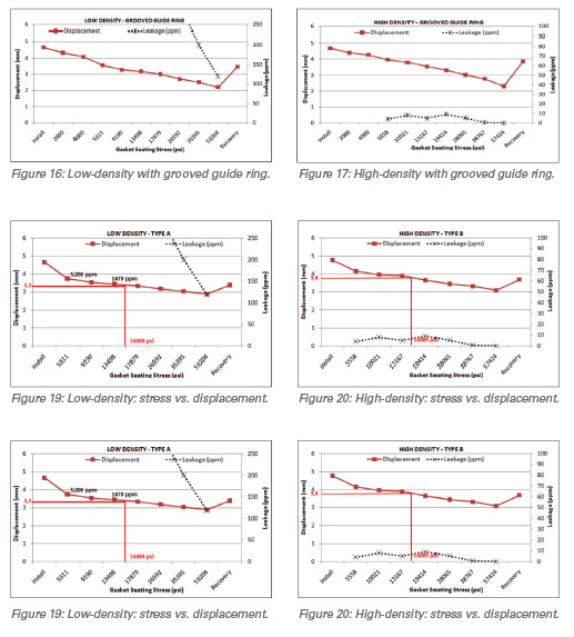
Conclusion
The sealing element’s winding density is a fundamental parameter for spiral wound gaskets. Low winding density is always correlated with worse sealability than the higher-density windings.The results of this testing helped to improve ASME B16.20: while the compression test remains in ASME B16.20, it has been altered such that the ‘finished gasket will compress to a thickness no less than 3.43 mm (0.135 in)’ when subjected to a uniform gasket stress. Previous versions of ASME B16.20 used low bolt stress instead of gasket stress.
However, the big improvement was the addition of the Performance Testing section in ASME B16.20-2017. This test has a leakage limit based on the circumferential length of the gasket’s outer diameter and requires multiple readings after a specified test pressure has been held for a minimum of four hours.
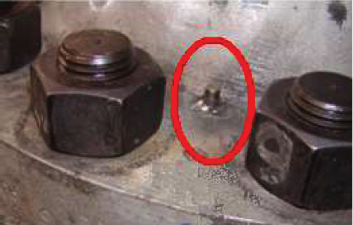 Figure 18: Measuring pin.
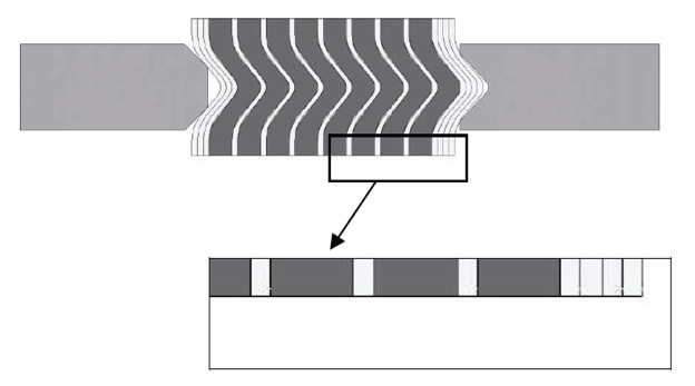 Figure 21: Flexible graphite filler flush with metallic windings.
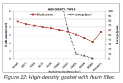 These changes to B16.20 have the ability to influence how manufacturers design and produce spiral wound gaskets. Why influence and not force? The ultimate responsibility of the enforcement of this standard does not lie with ASME. It is the responsibility of the end user to inspect and test the gaskets they are using. Refineries and chemical plants that are being tasked with reducing emissions and eliminating HSE incidents can lean on the research completed by Chevron and TEADIT in 2011 and require that all spiral wound gaskets that are used in US facilities are tested to and pass all elements of ASME B16.20-2017.
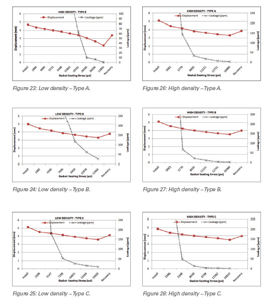
 About the Author
Jon Meyer is a Sales Engineer with Teadit. From Process Operator to Reliability Engineer, Jon has worked for nearly 20 years in the chemical manufacturing industry and holds a BE degree in mechanical engineering. As a Reliability Engineer, he was primarily focused on fixed equipment, Bolted Flange Joint Assembly training, procedures and torque calculations, 3D modeling, FEA for design and fabrication, heat exchanger design, glass-lined equipment, and non-metallics.