A heat exchanger (commonly abbreviated as HE or HX) is, at its most basic level, a system used to transfer heat between two sources. As such, they can be used in both heating and cooling applications. Traditionally, heat exchanger equipment comes in a variety of different styles, materials, and configurations. However, in industrial applications, one of the most common is the shell-and-tube style. These exchangers consist of a group of long slender tubes, called a tube bundle, which are confined within a vessel (or shell). Fluid is passed through the tubes, while a second fluid is passed through the vessel itself. These fluid sources are controlled at different temperatures and therefore heat/cool one another, hence the term heat exchanger. Heat exchangers are widely used in processes within power generation, chemical and petrochemical production, petroleum refining, natural gas processing, refrigeration, and more.
HE History and Design
The history of heat exchangers can be traced back to the 1880s. The first plate heat exchanger (PHE), another common style of exchanger which passes fluids along a series of thin plates, was introduced by Dr. Richard Seligman in 1923. Even modern internal combustion engines rely on heat exchanger technology in the form of engine coolant being cooled by the flow of air through the radiator coils. Early shell-and-tube exchanger designs first appeared in the early 1900s to meet the needs of burgeoning industrialization. Many of the uses for HE technology are still relevant today, however exchanger designs have advanced significantly since those early days, as have the codes and standards that govern their design.Since heat exchangers are carefully designed to achieve specific heat transfer results, the overall efficiency of the system relies heavily on the optimal performance of the equipment. Often times shell-and-tube exchangers will utilize a system of transfer “stages” by systematically circulating the fluids through a number of independent chambers. Without the proper flowrate through the system, efficiency can be lost. It is also imperative that the individual chambers be properly sealed to prevent passthrough leakage, which will also undermine the overall efficiency.
Gaskets play an important role in exchanger efficiency and performance. However, because of the nuances in exchangers and their broad usage in an array of services, there is no standard gasket style or material for heat exchanger applications. Rather, nearly any type of gasket can be used. Choosing the proper gasket requires careful consideration of both the equipment itself (fitment, available bolt size and strength, sealing surface condition, etc.) and the application (operating temperature and pressure, media, etc.). Most heat exchangers utilize a number of gasketed connections within the equipment, each of which needs to be considered individually.
A diagram of the sectional view of a typical shell-and tube-heat exchanger is shown in Figure 1. The location of some common components, such as the floating head, shell cover, tube-sheet, channel, and channel cover are indicated with black arrows; while the locations of gaskets are shown with red numbers.
These are generally referred to as:
1. Floating head gasket
2. Shell cover gasket
3. Shell to tube-sheet gasket
4. Channel box to tube-sheet gasket
5. Channel cover gasket
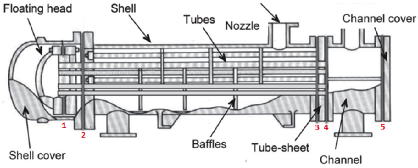 Figure 1: Heat exchanger diagram.
What is a Gasket?
From a standards and specification perspective, gaskets are often the most poorly controlled component of a bolted flange connection. Yet, they are a critical consideration in joint reliability. A gasket’s function is to seal the interface between two mating surfaces (most commonly flanges). At its simplest, its job is to keep the process media inside the system. Premature failure of bolted joint connections can lead to costly downtime, negative environmental impacts, and most importantly injury or even death. So, a lot is riding on the ability of a gasket to perform as expected.There are numerous different gasket styles to choose from for any given application. Determining which one is best suited for the job principally depends on several key factors, including: the size and construction of the joint components/flanges as well as their condition, the media being transferred through the system, the operating conditions (temperature and pressure), the amount load available/required to create an effective seal, the existence of excessive vibration or drastic changes in temperature and/ or pressure (cycling). All of these parameters will ensure that when a gasket is recommended, the integrity of the seal is upheld throughout the maintenance cycle of the equipment. In general, almost all gasket materials (including those used in heat exchanger applications) fall into one of two primary categories: non-metallic (or sometimes called ‘soft gaskets’) and metallic gaskets.
Non-Metallic Gasket Technology
Some common non-metallic gaskets utilized in heat exchanger applications are compressed fiber, flexible graphite, elastomers, and PTFE based materials. Each of these materials have certain characteristics that make them applicable for heat exchanger equipment based on the particular requirements of the application.Compressed fiber materials primarily consist of ‘non-asbestos’ aramid/synthetic fibers bonded by a rubber binder with inert fillers. While the usage of compressed fiber materials in heat exchanger applications is comparatively less common, these materials are still considered to be a good choice for general service HE applications and are suitable for various media including water, steam, air, mild inorganic acids, general chemicals, industrial oils, petroleum derivatives, and refrigerants. Compressed fiber gaskets can generally withstand temperatures up to around 400ºF and are suitable to resist pressures consistent with a class 300 flange rating (or equivalent).
Flexible graphite material is another gasket selection that is common in HE applications and is usually a better alternative to compressed fiber in terms of temperature rating and chemical compatibility. Flexible graphite materials are made from exfoliated graphite carbon flakes which are compressed into a foil and mechanically bonded together without the use of rubber or other binders and fillers, like those used in compressed fiber materials. Because flexible graphite is inherently fragile, these materials are commonly reinforced with thin layers of metal. These reinforcing layers not only improve handling, but also provide additional resistance to the system pressure when in service.
Flexible graphite materials can be enhanced with special additives (oxidation inhibitors) to allow them to perform well in environments up to 850ºF; while the range of chemical resistance that they offer is very broad and includes virtually all organic and inorganic fluids except for highly oxidizing acids.
PTFE (polytetrafluoroethylene, or commonly referred to by its trade name Teflon) is a synthetic fluoropolymer that offers unparalleled resistance to all common media ranging from 0 to 14 PH, with the exception of free fluorine and molten alkali metals. As a result, PTFE based materials are a popular choice in chemically aggressive applications. Virgin PTFE is highly susceptible to a mechanical phenomenon called ‘creep’ or ‘cold flow’ where the material essentially flows away from the applied load. This can be problematic in gasketing applications which rely on the material to resist load in order to maintain a long-term seal.
By adding fillers and restructuring the material to create a high level of fibrillation in the base structure, manufacturers have been able to reduce the amount of creep/ cold-flow in the material, giving it better mechanical properties in terms of compressibility and relaxation.
PTFE (particularly restructured PTFE mterials) are a recommended choice for aggressive service HE applications where the temperature rating does not exceed 500ºF.
Elastomer based gaskets are available in a variety of compounds and grades. Many of the common elastomer materials, including buna-nitrile, EPDM, neoprene, red rubber, silicone, and fluoroeslastmers (like FKM or Viton) can be used and each one offers different benefits and ratings based on the service media and temperature requirements. Specialty elastomeric gaskets are commonly used in plate heat exchanger applications.
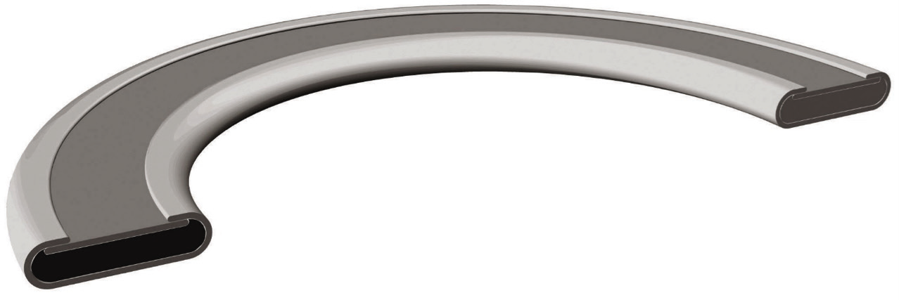 Figure 2: Double metal jacketed gasket.
Metallic Gasket Technology
While non-metallic ‘soft’ gaskets are a reliable choice in some exchanger applications, more often, metallic gaskets are the preferred/recommended option for a variety of reasons. The term metallic gaskets encompasses a wide range of different gasketing technologies, but many utilize some type of metallic structure combined with a soft sealing material like graphite or PTFE. These can often be referred to as semi-metallic due to the fact that they incorporate both metal and other materials in their respective designs. The major advantage of these types of gaskets is that they exhibit much less relaxation compared to non-metallic gaskets. Relaxation, in a nutshell, is a gasket’s tendency to lose load over time.Historically, the most commonly utilized style of semi-metallic gasket for sealing various parts of HE equipment has been the double-jacketed (DJ) gasket. Because shell-and-tube heat exchangers are designed in such a wide variety of shapes, sizes, and configurations – and because so many of their connections are non-standard sizes – DJ’s have been a popular choice due to the relative ease with which they can be manufactured to nearly any size, shape, or configuration.
Double-jacketed gaskets consist of an obround profile metallic ‘channel’ of two parts. The main part is a wide C-shaped profile referred to as the core, and second flat metal piece generally referred to as the lid that bridges the inside of the C-shaped opening. Both of these metallic sections are formed around a soft filler material such as graphite, PTFE, or compressed fiber material. The metal jacket can also be customized in nearly any metal material like carbon steel, stainless steel, copper, nickel, and even exotic alloys based on the requirements of the application and the operating conditions. Figure 2 shows a cutaway view of a typical double-jacketed gasket. This type of gasket can be further customized to incorporate various features, like corrugations single jacketed construction, and exterior facings.
Despite the fact that many (particularly older) heat exchangers were designed using double-jacketed gaskets, since the early 2000s a number of industry research re- ports have been presented through ASME’s annual Pressure Vessel and Piping Conference (PVP) that indicate that DJ’s exhibit relatively poor performance characteristics compared to a number of alternative gasket technologies, including: PVP2002-1081, PVP2008-61121, PVP2018-84907. In particular, PVP2002-1081.
Alternatively, another historically common gasket style utilized in HE applications is the corrugated metal gasket, or as it is commonly referred to in the industry, the ‘CMG’. The structure of this style allows it to exhibit good resistance to the radial shear and thermal cycling that is often present in many heat exchanger applications. CMG’s were first introduced in the latter half of the 1980s as the need arose for alternative gasketing technologies. Figure 3 shows a typical corrugated metal gasket with the facing partially removed. The structure consists of a metal core made usually from stainless steel which is corrugated by passing the material through specialized dies to form the proper profile and then faced with a compressible soft material layer like graphite or expanded PTFE on both sides.
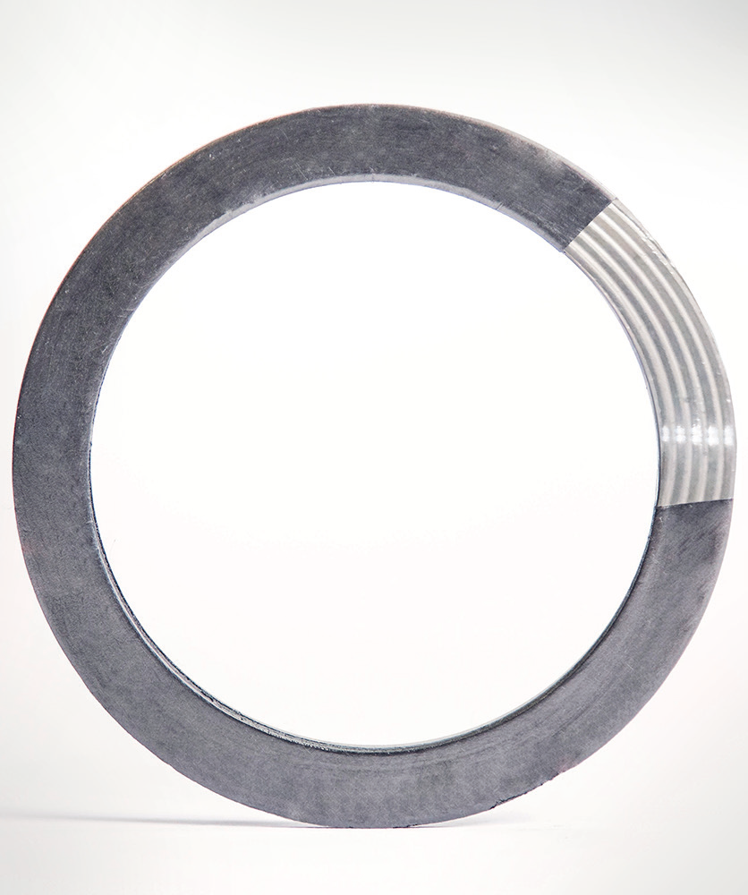 Figure 3: Corrugated metal gasket.
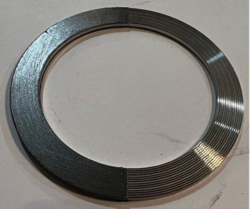 Figure 4: Camprofile metal serrated gasket.
Testing indicates that careful control of the corrugation profile (pitch) and the type and quality of the facing material will have a significant impact on the overall performance of a CMG. Unfortunately, there is currently no industry standard that governs corrugated metal gasket design, so performance can vary greatly from manufacturer to manufacturer.
As gasketing continues to evolve along with the challenges and nuances associated with industrial manufacturing applications, new materials and technologies continue to emerge. One semi-metallic gasket that has become increasingly more popular in exchanger applications is the camprofile gasket. Camprofile gaskets, or ‘campros’, consist of a solid metal core that is machined with serrations and then faced with a thin soft material like flexible graphite or expanded PTFE. They are a popular gasket choice due the fact that they are able to handle elevated temperatures and pressures; are highly customizable and can be made wide variety of shapes, sizes, configurations, and materials; and offer a tight seal at relatively low loads, especially when compared to most other styles of semi-metallic gaskets.
Campros are commonly manufactured as the core element only, as well as in styles which incorporate an outer guide ring to ensure proper alignment on the flange sealing surface on raised-face flanges. Figure 4 shows a typical camprofile gasket without an outer guide ring (the facing has been partially removed to show the serrated finish of the metallic core). This is the most common style of camprofile gasket used in HE applications due to frequency of male-female and tongue-and-groove flange configurations offered on typical shell-and-tube heat exchanger assemblies.
In Summary
Heat exchangers have a storied past as essential equipment in nearly every imaginable industrial manufacturing application. As the technology has become more advanced, the need for effective sealing has become more critical than ever. Selecting the proper gasket for a given exchanger application is not rocket science, but careful consideration of all of the pertinent information about the equipment and the application is crucial to making the best choice. Maintaining reliability of the jointed connections within the equipment is a must for optimal performance and efficiency, as well as the prevention of any catastrophic failures. With all of the various gasket technologies to choose from the questions is not often a choice between right or wrong, but rather a choice between good, better, and best. About the Author
Tarek Said is a Regional Sales Manager for the Teadit Group focused on providing customers with commercial and technical support to develop high performance and reliable sealing solutions. He is a degreed Industrial Engineer with over 16 years of experience working around the world in the fluid sealing industry specializing in field support and engineering applications.